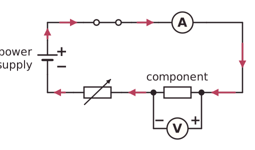
A circuit for testing a component is built as one series loop: a power supply, a switch, the component under test, an ammeter and, if wanted, a variable resistor. Because they are all in series, the same current passes through every one of them, so the ammeter reads the current in the component. An ammeter has a very low resistance, so it does not change the current it is measuring.
The voltmeter is the exception. It is connected in parallel across the component only, because it measures the potential difference between the two ends of that component. A voltmeter has a very high resistance, so it takes almost no current. If it were wrongly placed in series, the current would become very small and a lamp would stay off or barely glow.
A variable resistor in series lets the current be changed, so a range of readings can be taken. The switch is opened between readings so that the component does not heat up, because heating can change its resistance. Connect the meters the right way round, with the positive terminal towards the positive side of the supply.