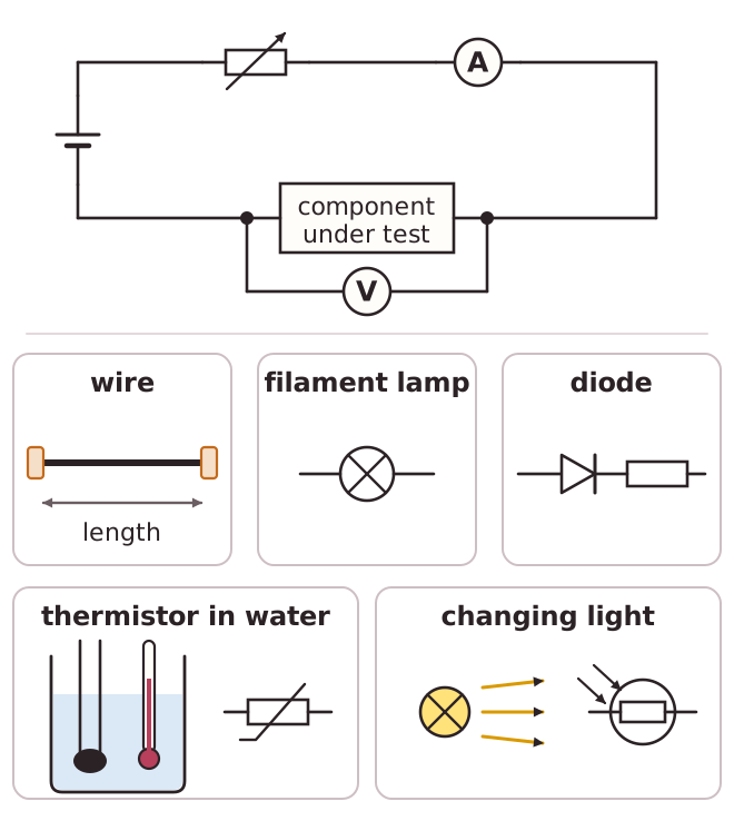
Simple d.c. circuits are used to measure the properties of components. An ammeter measures current, so it is connected in series with the component. A voltmeter measures p.d., so it is connected in parallel across the component. A voltmeter has a very high resistance so that it takes almost no current away from the component being tested. An ammeter has a very low resistance so that it does not change the current it is measuring.
To find the resistance of a component, measure the current through it and the p.d. across it, then use resistance = p.d. ÷ current. A variable resistor in the circuit changes the current and the p.d., so that many pairs of readings can be taken and plotted on a graph.
Circuits can also be used for testing. A cell, a lamp and two leads form a simple test circuit: if a wire or fuse connects the leads and the lamp lights, the wire or fuse is not broken.
Sensing circuits use a thermistor or an LDR in series with a fixed resistor. The supply p.d. is shared between them. When the light gets brighter, the resistance of the LDR decreases, so it takes a smaller share of the p.d. and the p.d. across the fixed resistor increases. This change can switch a device on or off, as in a light-operated switch or a temperature alarm.
For example, a p.d. of 6.0 V across a resistor with a current of 0.20 A gives a resistance of 6.0 ÷ 0.20 = 30 ohms.