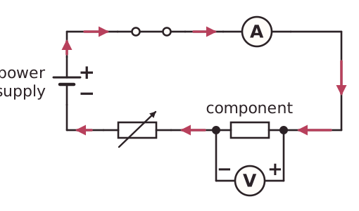
A series test circuit is built from a power supply, a switch, connecting wires, the component being tested and measuring instruments. The ammeter measures current, so it must be connected in series with the component, so that the same current passes through both. An ammeter has a very low resistance, so it does not change the current it is measuring.
The voltmeter measures potential difference, so it must be connected in parallel across the component, with its own branch joining the two ends of the component. A voltmeter has a very high resistance, so it takes almost no current and does not disturb the circuit. The circuit is drawn using standard circuit symbols.
To change the current in the circuit, a variable resistor is added in series. Moving its slider changes the total resistance, and so changes the current. A switch in series can be opened to break the circuit, so the circuit is only on while readings are taken. A student can then record matching readings of current and potential difference, and work out resistance with R = V ÷ I.