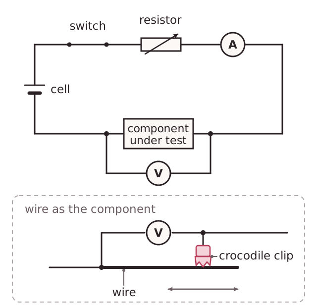
A d.c. circuit can be used to measure the resistance of a component and to test how it behaves. The component is connected in series with a cell (or power supply), an ammeter and a switch. The ammeter is connected in series so that the same current flows through it as through the component. An ammeter has a very low resistance so it does not change the current.
The voltmeter is connected in parallel across the component, because it measures the potential difference between two points. A voltmeter has a very high resistance so it takes almost no current from the circuit.
A variable resistor in series changes the current, which gives you a range of readings. To find the resistance, divide the potential difference by the current (R = V/I). The same circuit can test a thermistor in warm water, an LDR in different light, or a diode. To test a diode you reverse the connections and check that current flows in only one direction. You can then plot the readings as a graph.