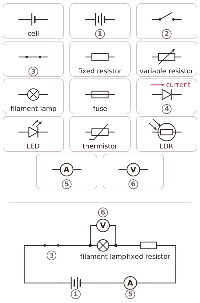
Circuit diagrams use standard symbols so that anyone can read them. Each component has its own symbol, and the components are joined by straight lines that stand for connecting wires. You need to be able to draw and interpret these diagrams.
A cell is drawn as one long line and one short line. Two or more cells joined together make a battery. A switch is drawn as a gap in the circuit, and it is open when the gap is left and closed when the gap is filled. A fixed resistor is a plain rectangle, and a variable resistor is the same rectangle with an arrow through it. A filament lamp is a circle with a cross inside it. A fuse is a rectangle with a line through its middle.
A diode is a triangle pointing at a bar, and the current can only pass in the direction of the triangle. An LED is a diode with two small arrows pointing away from it, because it gives out light. A thermistor is a resistor rectangle with a sloping line through it. An LDR is a resistor inside a circle with two arrows pointing towards it, because light shines on it.
Measuring instruments are drawn as a circle with a letter inside. An ammeter has the letter A and a voltmeter has the letter V. The ammeter is connected in series, in the same loop as the component. The voltmeter is connected in parallel, on a separate branch across the component.