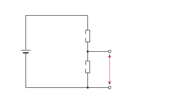
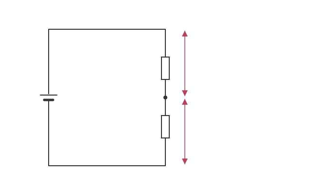
A potential divider circuit can be used to divide the potential difference to any value up to the maximum provided by the power source.A potential divider circuit consists of two resistors in series.The ratio of potential differences across the resistor is the same as the ratio of their resistances.
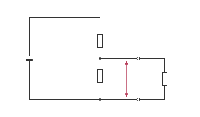
If a circuit is connected across one of the resistors the circuit will be supplied with the potential difference across that resistor.

Potential Divider Circuits
Read the text
Read the text and highlight anything you think is important. When you go on, the text is hidden and you answer from memory.
Specification: OCR Physics A (H156), AS-level, 4.3.3 Potential dividers. Topic: Electricity.
More in Electricity
- Kirchoff's Second Law
- Series Circuits
- Parallel Circuits
- Combining Resistors
- Analysing Circuits
- Internal Resistance
- The Potentiometer
- Sensing Circuits
All 30 lessons in Electricity · All OCR AS-level Physics topics